Rotork Electric Actuator Wiring Diagram
Switch loading will be limited to 5a.reliability to the limits at the heart of reliable valve control is the ability of the actuator to move on demand and. Close we use cookies in order to optimise this website and for continuous improvement.
Rotork Wiring Diagram Pdf Wiring Diagram
Rotork's own pakscan™ system offers advanced actuator network control similar to network control.
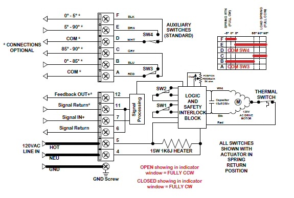
Rotork electric actuator wiring diagram. Resources for the ck range electric valve actuators, including drawings, literature and wiring diagrams english 中文 dutch français deutsch italiano 日本語 한국어 polski русский español Reliability standards have been set even higher, it is simpler to commission and use and is unrivalled in. Rotork electric actuator wiring diagram wiring diagram is a simplified adequate pictorial representation of an electrical circuitit shows the components of the circuit as simplified shapes and the skill and signal associates in the company of the devices.
The wiring diagram number identifies the electrical characteristics of the control system and motor. The wiring diagram number identifies the electrical characteristics of the control system and motor. Wiring direct to battery not recommended.
Apparently there is no 'standard' diagram for any given model for the basic power and drive signal connections. The rotork setting tool allows actuator control, indication and protection. The three times i was involved there there was no rotork wiring diagram with the actuator.
Every rotork actuator has been fully tested before leaving the factory to give years of trouble free operation, providing it is correctly commissioned, installed and sealed. Rotork actuator wiring diagram pdf download as pdf, txt or read "limit" • actuator wiring diagram does not vary with valve type. "intermediate" and "close" valve position indication (illuminated on syncropak).
For 60 years rotork has used innovation for designing reliable, flexible and robust valve actuators and control systems. The diagram number should be supplied to factory personnel if questions or problems arise concerning the. Rotork iq3 range actuators remote wiring schematics.
Rotork electric actuator wiring diagram wiring diagram is a simplified adequate pictorial representation of an electrical circuit it shows the components of the circuit as simplified shapes and the skill and signal associates in the company of the devices. 3.1 pipeline runs and actuator orientation recommendations 5 3.2 supporting the actuator for vertical pipelines 6 3.3 clearance for rising actuator 6 3.4 clearance for maintenance 7 3.5 pipe movement 7 3.6 pipe angular misalignment 7 3.7 flow direction 7 3.8 flange bolt torque requirements 8. Schematron.org 1 wiring diagram directory.
The diagram number should be supplied to factory personnel if questions or problems arise concerning the actuator control circuitry or electrical components. The diagram number should be supplied to factory personnel if questions or problems arise concerning the actuator control circuitry or electrical components. Reduced internal wiring and connections.
Reduced internal wiring and connections. Rotork actuators are compatible with a wide range of communication and process control systems. Drawings/dimension data standard a drawings:
Rotork is the global market leader in valve automation. The wiring diagram number identifies the electrical characteristics of the control system and motor. The diagram number should be supplied to factory personnel if questions or problems arise concerning the actuator control circuitry or electrical components.
Search for rotork documents, publications, literature, product catalogues, manuals Rotork valve actuator wiring diagram wiring diagram is a simplified customary pictorial representation of an electrical circuit it shows the components of the circuit as simplified shapes and the capacity and signal contacts along with the devices. This brochure provides a comprehensive overview of the applications and associated functions available with rotork cva actuators.
Rotork wiring diagram rotork wiring diagrams the wiring diagram selector returns standard iq iqt iq3 ck ckr ckc ckrc cva and cma wiring diagrams only for specials or if you can t find what you want rotork b rotork document search area search for and download documents wiring diagrams and product drawings. Their impact on control and variability. Wiring s12 diagram iq rotork wd5r trusted diagrams rotork wiring.
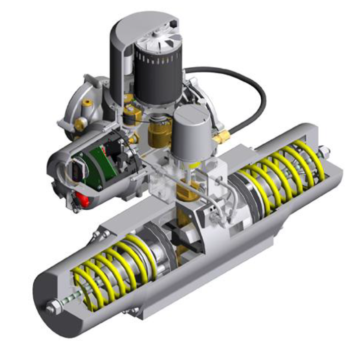
Diagram eh3 description p/n examples wire code page heavy duty actuator model "eh5" warning: The wiring diagram selector returns standard iq3/iqt3 range wiring diagrams only. Rotork valve actuator wiring diagram wiring diagram is a simplified customary pictorial representation of an electrical circuit.
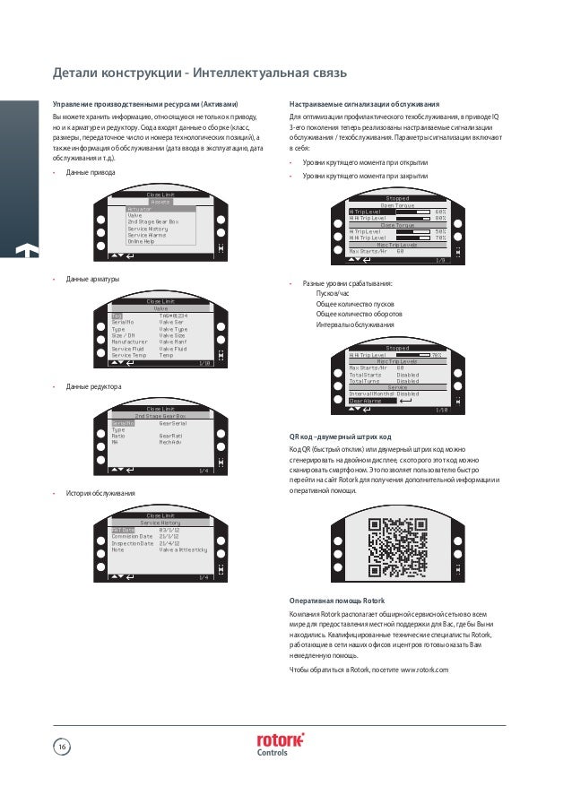
For specials or if you can't find what you want, please contact rotork. The 3rd generation iq intelligent actuator. Each time rotork's telephone tech support required the model number and serial and had to 'go look it up' and send the wiring diagram later on.
100b00006 Electrical Components Computer Engineering

ROTORK K SERIES ACTUATOR WIRING DIAGRAM Auto Electrical Wiring Diagram
[DIAGRAM] Wiring Diagram Rotork FULL Version HD Quality Diagram Rotork PAINDIAGRAM.ARGISO.IT

Rotork Motor Operated Valve Wiring Diagram Wiring Diagram Schemas

Rotork Wiring Diagram Awt Wiring Diagram

ROTORK K SERIES ACTUATOR WIRING DIAGRAM Auto Electrical Wiring Diagram

ROTORK K SERIES ACTUATOR WIRING DIAGRAM Auto Electrical Wiring Diagram

ROTORK K SERIES ACTUATOR WIRING DIAGRAM Auto Electrical Wiring Diagram

Rotork Motor Operated Valve Wiring Diagram Wiring Diagram Schemas

Rotork Iq Wiring Diagram micoledeinfantil
Rotork Motorised Valve Wiring Diagram Wiring Diagram

Rotork Motorised Valve Wiring Diagram Wiring Diagram

ROTORK K SERIES ACTUATOR WIRING DIAGRAM Auto Electrical Wiring Diagram

ROTORK K SERIES ACTUATOR WIRING DIAGRAM Auto Electrical Wiring Diagram


